The unyielding foundations rule
The unyielding foundations rule: It is easier to change a module than to change the modularity.The reason is that once an interface has been used by another module, changing the interface requires replacing at least two modules. If an interface is used by many modules, changing it requires replacing all of those modules simultaneously. For this reason, it is particularly important to get the modularity right.
— Saltzer & Kaashoek, Principles of Computer System Design: An Introduction, 2009. (pdf)
As makers and engineers, the first things we built were probably small and simple. Early activities might have looked like a "hello world" program, a simple webpage, an Arduino sketch to blink the built-in LED, or a basic shape on a 3-D printer or laser cutter. We keep learning and improving our building skills, and we start realizing just how useful our creations can become. But as we apply our initial skills to larger and more interesting problems, we start hitting up against unexpected limits where it should be easy to add just one more small feature to a project, but in practice it's a whole ordeal:
- It could look like a circuit board where you can't implement the features which your collaborator has recently added to their wishlist, because you've used up too many of the pins on your 60-pin Arduino board.

- It could look like a mechanical design which uses so many dimensional constraints and parameters that your CAD software freezes for a full minute whenever you make changes which force it to rebuild the whole model.

- It could look like a 2000-line single-file Arduino sketch where you've gradually added pieces of code and now you have 150 global constants and 150 global variables and 40 functions, with each function possibly interacting with up to all 300 of those global constants and variables.

- It could look like a multithreaded Python implementation of a serial communication protocol which occasionally deadlocks in ways you can't consistently reproduce, and it happens because of how you initially decided to integrate I/O operations with protocol logic

Maintaining the project becomes painful and difficult because we let our designs become complex without responding appropriately to that complexity. But it doesn't have to be like this.
Ignoring complexity will make it harder.
When we design things to meet many requirements or to achieve a few ambitious requirements, technical complexity becomes a big challenge. We can face it from the start, or we can risk doing a lot of work to get exciting early results but needing to redesign everything from scratch at an inconvenient future moment in order to be able to add our next feature to get more results. In academic science labs, I usually see the latter approach, because a rough prototype made as a proof-of-concept ended up being extended far beyond what its initial design was good for: the designer didn't deal with how complex the system was becoming, so their subsequent development made the system even more complex. Even when we do plan ways to manage complexity, we'll still eventually need to do a redesign - but hopefully we'll at least have a faster way forward or a better starting point.
Fortunately, the field of systems engineering gives us useful tools to cope with complexity in designing and maintaining systems. In Principles of Computer System Design, Saltzer & Kaashoek give a working definition of a system as "a set of interconnected components that has an expected behavior observed at the interface with the environment".
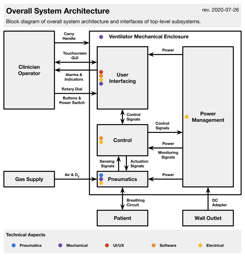
Depending on our design goals for a system, different things may be relevant to us as the components, the system, the interface, and the environment. For example, here is my functional block diagram describing the Pufferfish ventilator at a high level:
Fig. 1: Functional block diagram of the overall design of the Pufferfish ventilator. The mechanical enclosure defines the boundary between the system and environment. The grey blocks are high-level components which themselves consist of lower-level components. The arrows show the interconnections between various components, as well as the interface with the environment.
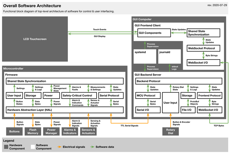
And at one lower level of detail, here is my functional block diagram describing the overall design of the Pufferfish ventilator's software. It breaks the "User Interfacing" and "Control" blocks from Fig. 1 down into many smaller components. This high-level design has been stable for the past 6 months, even as the design within each individual block has changed. From the number of boxes and arrows in this diagram, you can tell that there's a lot going on in the software of this ventilator, but most components have interconnections with only a few other components so it's relatively straightforward to follow how information flows through the system:
Fig. 2: Functional block diagram of the overall design of the software of the Pufferfish ventilator. The software consists of three domains running on two separate processors: safety-critical firmware running on an STM32 microcontroller, a graphical frontend running in a web browser on a Raspberry Pi single-board computer, and a Python backend WebSocket server on the computer to service the frontend and the firmware.
Saltzer & Kaashoek emphasize complexity as a practical, subjective property of systems: systems are complex when they're difficult for us to understand at the levels we care about. System complexity is associated with having many components, having many interactions between components, having many irregularities or exceptions, requiring many words to describe what the system does, or being impossible for one person to fully understand or maintain. Complexity can come from the number of requirements a system must meet, from non-obvious interactions between each requirement, and from changes in the stated requirements over the lifetime of a system (such as to account for unforeseen requirements).
These sources of complexity are why I've seen so many systems designed by academic-scientists-who-don't-consider-themselves-engineers (especially data analysis or computational modeling software) which are too difficult to understand by anyone other than the initial designers: as the designers add more requirements to support more and more interesting experiments, in the short term it's faster for them tack on features in an improvised way without dedicating time to revisit the system's underlying design. This matters because these developers prioritize getting scientific results quickly over making a system easy to improve and extend for future experiments - after all, results are needed to show that a system is useful enough to develop further. And so technical debt accumulates at the foundations of the design of these systems, ironically making it harder for future people to build on the previous work used to generate these exciting results. But all designers of interesting systems, whether scientists, engineers, hobbyists, or otherwise, have probably fallen into this pattern on several projects. And so we all need ways to reduce complexity in the systems we build so that we - and other people - can understand what we did in order to carry our work forward.
Modular design helps manage complexity.
Saltzer & Kaashoek identify four general categories of common techniques for coping with complexity, used across many different engineering fields: modularity, abstraction, layering, and hierarchy.

Modularity is a strategy of dividing a system into interacting subsystems, which we call modules, in a way that we can consider each one separately. We can think about interactions among components of a module without also having to juggle components inside other modules. It's easier to troubleshoot a system by first identifying the faulty module instead of having to look at every single component in the system. And it's easier to improve a system by improving and replacing a module instead of completely rebuilding the system. Modularity helps a designer allow for uncertainty, experimentation, and future changes: as long as the design rules for a system's modularity are followed, the system can be improved later, potentially in unforeseen ways.

Abstraction is a requirement to separate out the interface of a module from its implementation so that any module can interact with other modules only through their interfaces, ignoring their internal implementations. Saltzer & Kaashoek introduce abstraction as an additional requirement on modularity: for a modular design to be useful, it should limit the interactions among modules, and the effects (and problems) which can propagate from one module to another. To prevent accidental or hidden interconnections from sneaking through/around interfaces and causing problems, designers in computer systems can use various techniques to enforce modularity. In practice, most abstractions are "leaky" and can't perfectly hide the implementation under the interface.

Layering is one way of organizing modules to reduce interconnections by using one complete set of mechanisms (a lower layer) to create a different complete set of mechanisms (an upper layer); each layer may be implemented as several modules. To reduce interconnections, a module of one layer should only interact with other modules in the same layer and with modules in the next higher and lower layers.

Hierarchy reduces interconnections among modules differently than layering: a small group of modules is combined into a stable, self-contained subsystem with a well-defined interface; then a small group of subsystems is combined into a larger subsystem with a well-defined interface, and so on until large subsystems are combined to form the overall system. Hierarchy constrains interactions by only allowing them among the components of a subsystem. This lets the system designer develop one subsystem at a time, focusing only on interactions between the interfaces of the components within the subsystem.

Each of these techniques is used to reduce complexity in the design of the Pufferfish software (Fig. 2). Every block in Fig. 2 is a module. Hierarchical design keeps the modules within each of the Microcontroller Firmware, GUI Backend Server, and GUI Frontend Client subsystems separated, except by two arrows which correspond to the interfaces between the three subsystems. Those interfaces allow us to keep those subsystems running on entirely separate processes/processors, so that enforced modularity allows us to keep the Microcontroller Firmware running even if the GUI Backend Server crashes; because of the abstraction provided by this interface, the Microcontroller Firmware can completely ignore the implementation details of the software on the GUI computer. Layered design within each of these three subsystems allows modules for higher-level logic to be separated from modules for low-level I/O or hardware operations by modules for drivers and protocols in intermediate layers. All four techniques are also applied recursively to the design within each software module shown in the diagram. Thus, although the Pufferfish software is doing a lot of things, we've been able to keep complexity at a manageable level - at least for now.
Case study: modularity emerges in redesign of the Octopi microscope driver electronics.
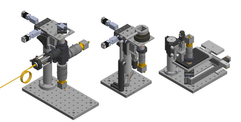
To give a concrete illustration of when these techniques are useful and how they can be applied in practice, I'll describe the evolution over three iterations of the design of the driver electronics system for the Squid microscope. Squid, short for Simplifying quantitative imaging platform development and deployment, is a toolkit for implementing microscopes with advanced imaging capabilities comparable to what's available in commercial solutions, but at a fraction of the cost ($500-$10k vs. $50k-$120k) and with much higher portability:
Fig. 3: CAD renderings of Squid with motorized stages and focusing mechanisms in three configurations, from left to right: 1) an inverted configuration for multi-color flat field epifluorescence microscopy with organism tracking, 2) the simplest inverted configuration, and 3) an upright configuration for reading 96-well plates. By Hongquan Li, from the website for the Squid project.
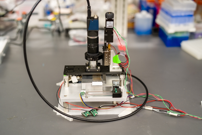
For comparison, Squid's predecessor is the Octopi microscope, a lower-cost upright design specialized for malaria diagnostic microscopy in field settings, with two optomechanical modules:
Fig. 4: Photograph of the Octopi microscope. The upper half of the image shows the imaging module with a piezoelectric focusing mechanism, while the lower half of the image shows the motorized X-Y stage and illumination components. Driver electronics are not shown in this image. By Hongquan Li.
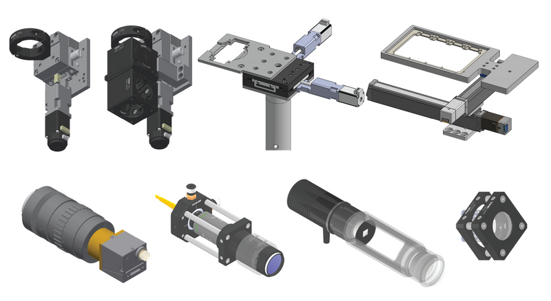
While Octopi only used custom-designed machined metal parts for the mechanical and optical subassemblies, and its design was optimized for scanning sample slides, Squid is intended to be a more general design with more versatility and configurability. Since the start of the Squid project, the optical and mechanical subassemblies have been a modular system of microscope building blocks consisting of structural parts from Thorlabs and custom-designed machined parts, with the modules composable in ways that allow for easier customization and configurability as well as prototyping of new functionalities:
Fig. 5: CAD renderings of various building blocks for Squid, consisting of motorized focus blocks, motorized sample stages, image formation assemblies, and illumination modules. By Hongquan Li, published under CC-BY-NC-ND 4.0 in the Squid project's Jan 2020 bioRxiv preprint.
The goal is for labs to quickly build a potentially large number of compact advanced microscopes to their exact needs by mixing and matching these modules, and at a much lower cost per microscope than commercial products with similar capabilities. But while Squid's optical and optomechanical design have been modular from the start, the electronics for driving the various sensors and actuators in these modules (e.g. lights, lasers, motors, encoders, and limit switches) started with a monolithic design and have been evolving towards greater modularity over several design iterations, for several interesting reasons which I'll discuss next.
Iteration 1: A monolithic design reveals important limitations.
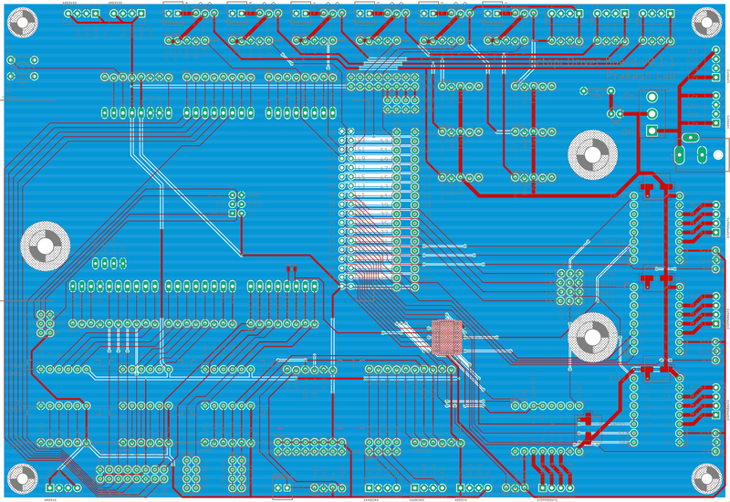
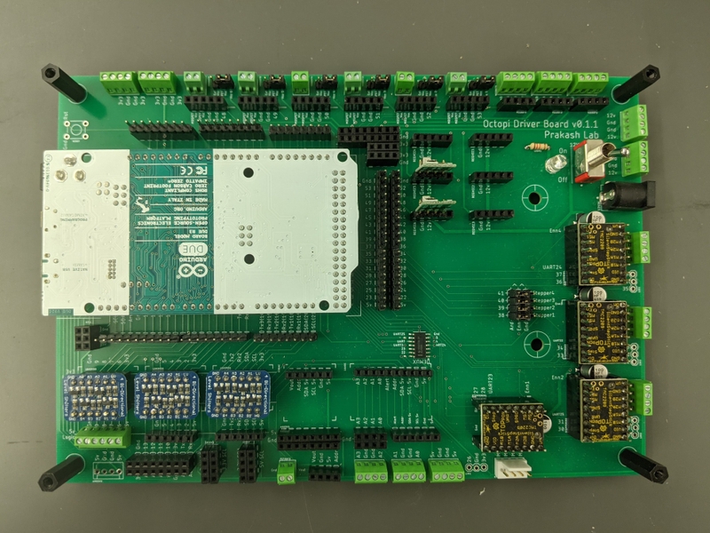
For Octopi and early prototypes of Squid, most actuators in our system were driven by a fixed set of off-the-shelf boards, and we just needed a way to integrate those boards with connectors for easier assembly. The project initially wanted to have a single circuit board to drive everything from an Arduino Due, so it made sense to start with a relatively monolithic design; and for historical reasons we called this board the Octopi driver. This required us to plan for every possible way the board might need to be used, from prototyping to production use, from basic configurations to advanced configurations, and allowing for future optical modules. The result was that requirements kept being revised and added, which made the design process slower and more difficult, and which forced a design with restrictive layout limitations:
Fig. 6: Layout (top) and assembled (bottom) PCB for the first design iteration of the driver electronics for the Squid microscope, designed as a monolithic board. Almost all components are through-hole connectors. Connectors for an Arduino Due are on the left, while connectors to off-board components are on the top, bottom, and right edges of the board.
While in retrospect this board is not that complicated, it was only the fourth PCB I had ever designed. But I quickly realized that it would be difficult to maintain and expand this design in order to support requirements which continued to be added during and after this design iteration.
The primary source of layout difficulty was a set of many requirements for screw terminal blocks as connectors for off-board components, which meant those connectors all needed to be at the edges of the boards for access. This meant that most of the daughter boards exposed by these screw terminal connectors had to be near the edges, and since screw terminals generally come as through-hole components, we could only have connectors on one side of a PCB. Because the size (area) of the board scales quadratically against the perimeter of the board, and because the Arduino Due's pins would need to be routed to components at all edges of the board, we had a large number of constraints and interdependencies for board layout and routing. In other words, there were many spatial relationships interconnecting the many components in the system.
Iteration 2: Physical modularity demonstrates advantages.
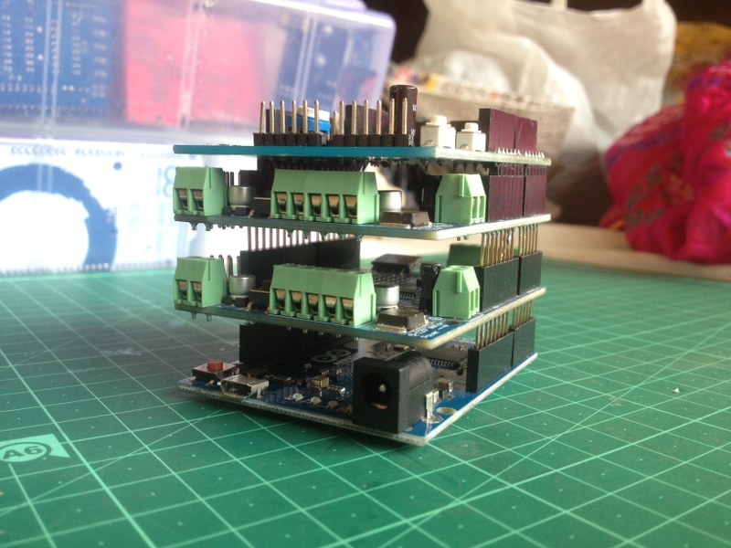
Recognizing that the limiting factor in our board design was free space at board edges for connectors and the number of traces which needed to be routed to various components, and that we were likely to need even more connectors in the future, we decided to take a different - hopefully easier and faster - approach for our next design iteration of the Octopi/Squid driver electronics. We took inspiration from the Arduino's design for stackable shields:
Fig. 7: Photo of an Arduino board with three shields stacked on top. By Kushagra Keshari, published on Wikimedia Commons under CC BY-SA 4.0.
So the next design iteration of our board electronics added the same kind of physical modularity to our system as is found in Arduino shields. By putting different components on different PCBs, we greatly reduced the number of spatial relationships interconnecting the components. And using multiple PCBs all in a stack removed the need to use 4-layer or 6-layer PCBs to make trace routing feasible, as 4-layer and 6-layer PCBs much more expensive to fabricate than 2-layer PCBs.
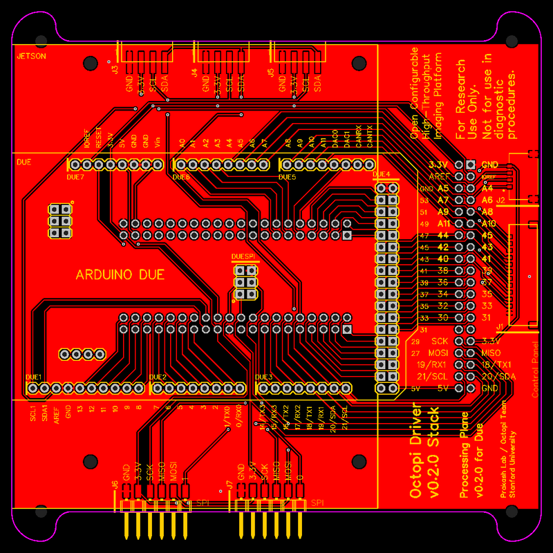
As a proof-of-concept, I designed one board (which I call a "processing plane", because it does the computation and processing in the system) to break out an Arduino Due into a uniform set of stacking header connectors and to expose some other pins through connectors at the board edges (e.g. for a control panel or for prototyping with off-board I2C and SPI devices):
Fig. 8: PCB layout of components and routing of traces on the processing plane for the second design iteration of the driver electronics for the Squid microscope. Stacking header connectors and headers for the Arduino Due are through-hole components, in the middle of the board. Molex Pico-Lock connectors for a control panel are on the right edge of the board. Connectors for I2C and SPI buses are on the top and bottom edges of the board, for prototyping use. Mounting holes for an NVIDIA Jetson Nano single-board computer are around the area for the Arduino Due, while the corners of the board have mounting holes for standoffs to hold the stack of PCBs together.
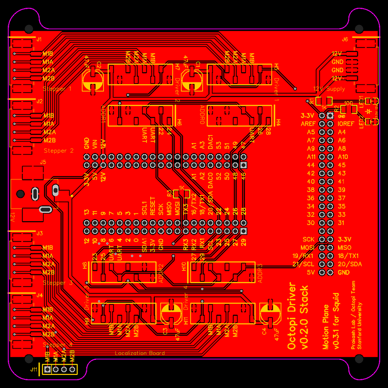
And then I designed one module (which I call a "motion plane", because it does motion control for the motors in the Squid microscope) which stacks under the processing plane and uses some pins from the stacking connectors to control some stepper motor driver boards, whose outputs are exposed through connectors:
Fig. 9: PCB layout of components and routing of traces on the motion control plane for the second design iteration of the driver electronics for the Squid microscope. Stacking header connectors are in the middle of the board. Surface-mount spring-cage terminal blocks as connectors for stepper motors are at the left edge of the board. Surface-mount headers for TMC2209 SilentStepStick stepper motor driver boards are above and below the stacking header connectors. A DC barrel jack for 12 V motor power supply is at the middle of the left edge of the board. A spring-cage terminal block for the 12 V power supply is at the right edge of the board, for prototyping purposes.
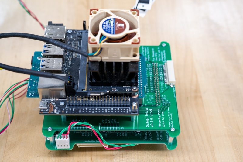
These boards were successfully integrated into a stacked design which worked well:
Fig. 10: Photograph of the processing plane stacked on top of the motion plane. An Arduino Due and NVIDIA Jetson Nano are mounted on the processing plane. By Hongquan Li.
During the process of designing this stacking modularity, I realized a few important lessons:
- Because we needed many connectors at board edges but we didn't really need access to components from above or below the board, stacking multiple PCBs allowed us to use space more efficiently than in a monolithic design; our stack could add as much functionality as we wanted, all while staying within a 4.5" x 4.5" footprint.
- Because I designed a uniform pin connection interface for the stacking headers, I could defer design decisions for different modules. So I could design the motion plane without having to account for or commit to the constantly-changing requirements for a future illumination plane to control lasers and LEDs the way I had to when I was laying out all components for all functionalities on the same board in the monolithic design. This modularity also let us assemble and test modules independently before committing to design decisions on other modules. This goes back to the concepts of modularity and hierarchy as discussed by Saltzer & Kaashoek.
- Because functionalities were divided into separate modules, we could easily fix errors, change components, or upgrade one module without having to reassemble the entire system, the way we needed to do in the previous design iteration. For example, when we needed to change the connector on the processing plane for some off-board components because the connector had stopped being produced, we just needed to replace the processing plane, and we could keep using the same motion plane as before.
- Because it became easier to add future requirements or functionalities by adding or upgrading or making variations on modules, it became easy to imagine developing design variants for special microscopes beyond the core design.
This design was also successful in that other projects my lab is involved in have started using the Octopi/Squid driver stack, even with only the processing plane and motion plane, and they have been using it beyond any applications I had planned for. Early prototyping work in the Pufferfish ventilator project used this version of the driver stack as the core of the ventilator electronics, with many of the unassigned GPIO pins used for new sensors in the prototype:
Fig. 11: Timelapse video of assembly of an early prototype of the Pufferfish ventilator, which included the Octopi driver stack as a key component. Assembly of various additional electronics onto the driver stack begins at 01:52 and finishes at 02:39. By Hongquan Li.
And this driver stack, as part of Squid, is also being used in multiSero, a multiplex-ELISA platform for analyzing antibody responses to SARS-CoV-2 infection (link to bioRxiv preprint by Byrum, Waltari, et al. will be added when the preprint is uploaded).
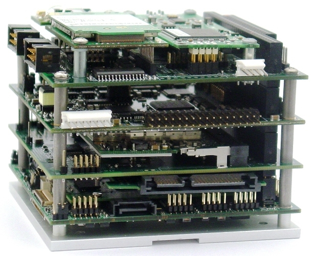
As an interesting sidenote, I later found that a similar concept, using 0.1" pitch stacking through-hole headers and standoffs to integrate PCBs into a stack, is also used in the PC/104 industry standard for modular embedded computers:
Fig. 12: Example of a PC/104 stack consisting of a a single-board computer and I/O modules. The stacking headers can be seen near the right edge of the mechanical structure. Photograph by Diamond Systems.
Iteration 3: More modularity becomes necessary.
Because other labs have started using Squid and my lab is looking to scale up our own deployment of Squid for various lab members's projects, we needed to improve the design of our Octopi/Squid driver stack to make it easier and faster to assemble at a reasonable cost. In particular, we decided to use surface-mount parts (especially for the stacking connectors) instead of through-hole parts wherever possible, so that we could assemble most of our PCBs through affordable surface-mount assembly services. Because it'd be nontrivial to modify the second design iteration for this change, and because the list of requirements and desired functionalities for Squid had also grown drastically, I decided to do a clean-sheet redesign for the third iteration of our driver stack.
The most interesting design change in this iteration is a shift from directly using GPIO pins on our microcontroller to using SPI devices for I/O, in order to support the much greater number of devices we intend to connect to the microcontroller. The shift to SPI devices was necessary because controllers like the Arduino Due - which already have around 60 GPIO pins - simply don't have enough pins to talk to all the sensors and actuators which will need to be simultaneously integrated into certain configurations of Squid microscopes. As an additional benefit, moving all I/O to communication over SPI removes the complication of dealing with budgeting and assignment of GPIO pins from the microcontroller for various components, and it allows almost all GPIO pins to be freed up for future prototyping uses.
This shift is accompanied by my introduction of a way to indirectly address each SPI device from among a set of many devices, so that I don't need to allocate one more GPIO pin on the microcontroller for each SPI device I add to the driver stack. Using this kind of hierarchical modularity to organize the I/O interfaces of the SPI devices on the planes seems very promising to me. First I'll explain how it works, then I'll describe the opportunities it may enable for the Squid microscope, and finally I'll discuss some open questions and potential limitations of this design.
All problems in computer science can be solved by another level of indirection, except for the problem of too many levels of indirection.(attributed to David Wheeler)
Adding two levels of indirection enables hierarchical modularity for I/O.
My system for addressing SPI devices allows each of up to 256 SPI devices in the driver stack to be selected one-at-a-time using just one SPI bus and three GPIO pins from the microcontroller, by multiplexing the chip select pins for SPI devices over those three GPIO pins. Before I describe how I address SPI devices spread over multiple planes in a stack, I'll first describe how I address SPI devices in a single plane.
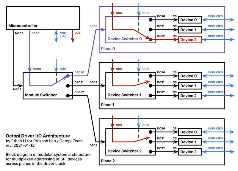
The basic idea is that each plane in the driver stack will have a module which acts as a chip-select demultiplexer and consists of an SPI-controlled GPIO expander chip (e.g. the MAX7317) connected to an analog multiplexer chip (e.g. the 74HC4067). These two chips together act like a MAX349 chip, but they allow demultiplexing one line over 16 lines instead of over just 8 lines. This allows an SPI command to connect zero or one of N=16 pins to a GPIO pin from the microcontroller, which is named DCS (short for "Device Chip Select") and is shared across all planes in the driver stack. The chip select pin of each of up to 16 SPI devices on the plane can be connected to one of those 16 pins from the chip-select demultiplexer, so that the microcontroller can select a particular SPI device by first sending the corresponding SPI command to the chip-select demultiplexer and then setting the microcontroller's DCS pin to active. Because this chip-select demultiplexer is used to select the DCS pin of a particular SPI device on the plane in order to switch between different SPI devices, I call it a "Device Switcher":
Fig. 13: Block diagram showing the hierarchical modularity for individually addressing SPI devices distributed over multiple planes. Blue lines denote the CIPO and COPI data lines of the SPI bus shared across all SPI devices in the system. Purple lines denote the connected signal path for the DSCS line; the Module Switcher has been set by an SPI command to connect the DSCS pin of the Device Switcher in Plane 0 to the DSCS pin of the microcontroller. Red lines denote the connected signal paths for the DCS line; the Device Switcher in Plane 0 has been set by an SPI command to connect the CS pin of Device 2 in Plane 0 to the DCS pin of the microcontroller, while the Device Switchers in the other planes were set by previous SPI commands to disconnect the devices from the DCS pin of the microcontroller. At any given moment, only one of the MSCS, DSCS, and DCS pins is allowed to be active. In this diagram, only three of up to 16 planes are shown, and only three of up to 16 SPI devices per plane are shown. The implementation of this design can be reviewed on Github.
Note that the Device Switcher has its own chip select pin which must be different from the DCS pin, so I call that chip select pin DSCS, short for Device Switcher Chip Select. So now we can address up to 16 SPI devices on a plane just using an SPI bus shared across all planes, a DCS pin shared across all planes, and a DSCS pin uniquely assigned to each plane. But how do we address the Device Switchers in order to send a command to only one Device Switcher at a time, when we have multiple planes stacked together?
As Fig. 13 shows, we can assign a minimal number of GPIO pins from the microcontroller for addressing different Device Switchers by the same chip-select demultiplexer to multiplex 16 pins (DSCS0, DSCS1, ..., DSCS15), each of which will be uniquely assigned to the Device Switcher for a particular plane, over a single DSCS pin from the microcontroller. Then plane 0's Device Switcher will listen to DSCS0 as its DSCS pin, plane 1's Device Switcher will listen to DSCS1 as its DSCS pin, and so on. Because this chip-select demultiplexer is used for switching between different planes, which are the high-level modules of the driver stack, I call it a "Module Switcher", and I call the chip select pin of its GPIO expander MSCS, short for Module Switcher Chip Select. The Module Switcher is placed on the processing plane which has the microcontroller, and it acts as the root of a two-layer address tree for selecting SPI devices.
This addressing scheme allows us to expose a simple, uniform I/O interface for each plane, independent of the number or types of SPI devices on the plane, and independent of which planes are in the stack. Each plane just:
- shares the CIPO and COPI lines of an SPI bus
- shares the DCS line
- reserves one of the 16 available demultiplexed DSCS lines out of DSCS0, DSCS1, ..., DSCS15
Because each plane only reserves one pin for its personal use, we've almost entirely prevented planes from making any unintentional interconnections, and we've grouped the SPI devices within each plane into an electrically self-contained subsystem which is functionally independent of the SPI devices in other planes, with a clean and small communication interface to the outside world. In other words, the Octopi/Squid driver stack is now hierarchically modular not only in its physical structure (as it was in the second design iteration of the stack), but also in its I/O communication interface.
Hierarchical modularity allows arbitrary combinations of planes in the driver stack.
We can use jumper wires, header pin jumpers, solder jumpers, or jumper resistors to (re)configure which demultiplexed DSCS line a given plane listens to. So if we always have 16 or fewer planes in a stack, then we can always remove any possible collisions resulting from two planes listening to the same demultiplexed DSCS line. Then it will always be possible to place any combination of 16 planes into a stack. So this removes the need to worry about pin budgets on the microcontroller or about multiple planes using the same pins on the microcontroller. So anyone can design an application-specific plane (e.g. a plane to pump fluids or control temperature gradients for a particular experiment) and guarantee that it can be integrated into the driver stack without any I/O issues, as long as it only uses SPI devices for interfacing with the microcontroller.
Another consequence is that we can put multiple copies of the same plane into a stack, as long as we make them listen to different demultiplexed DSCS lines. This was not possible in the previous design iteration. For example, in the previous design iteration, the motion plane only had space to independently control four stepper motors; if someone wanted to build something with eight stepper motors (which did become a need in prototyping for the Pufferfish project), then they had to accept that they would always be driving two stepper motors simultaneously, if they stacked two copies of the motion plane together. In this new design, if someone needs to drive eight stepper motors independently, then they just need to add another motion plane to the stack and change a jumper.
To summarize, the additional modularity in this third design iteration of the Octopi/Squid driver enables really powerful flexibility and customizability in the driver electronics, perhaps enough to keep up with the flexibility, customizability, and functionality demonstrated in the optomechanical subsystems of the Squid microscope. This comes at the cost of additional complexity in the electronics and software of the system - it seems well-suited to research use where reconfigurability, prototyping, and expandability are important priorities, but I would not use it in a life-critical medical device.
Modularity in electronics is limited by the laws of physics.
While this design seems promising for the Squid project's requirements, I'll need to test it out to determine how well it actually works. In particular, there's one big concern I have about the way I'm sharing the CIPO and COPI lines of a single SPI bus stretched across many planes, as well as with SPI devices outside the driver stack which are connected to the driver stack by long wires: reflections of signals on long conducting lines. Because I haven't learned about high-speed digital signal integrity, I don't have a good intuition for how concerned I should be with ~25 MHz SPI signals (with rise times on the order of a nanosecond or even less) routed through many connectors and stretching over a total length of around 12 - 24 cm or even up to 50 cm. A back-of-the-envelope analysis suggests that my design may be in a regime where signal reflections start becoming relevant. If so, source termination or end termination resistors may be able to solve this problem, potentially at the cost of significantly higher power consumption. Right now I'm crossing my fingers and hoping that I've kept the lengths of signal paths low enough that I can scrape by without having to figure out termination for signal reflections, and I'll just have to test the stack in various configurations to see what happens.
It's clear: even if we have a great modular design, there is a physical limit to how much can we scale up the number of modules or SPI devices supported by the Octopi/Squid driver stack, because at some point we will run into signal integrity problems. But all that matters is whether we can meet the requirements for the Squid driver electronics before we run into those problems, and that's something we'll have to figure out as we go.
Learn by doing.
I hope the concepts and case study discussed in this post have helped you think about modularity from more perspectives and about how modularity can help you to design systems. But really understanding this at a deeper level requires trying to design systems well, paying attention to what works and what doesn't, and learning from the mistakes you will make. Here's what I've been practicing, due to lessons learned from my past mistakes:
- Each time you start designing a system or hit some limit in what you've designed, first pause and do some brainstorming to (re-)clarify what requirements your system will need to meet, what future requirements might arise, and what areas you don't understand well enough to identify clear requirements.
- Design for iteration. Unless you're planning to stop developing or using your system, you'll need to redesign modules or the modularity as your system, its requirements, and your understanding evolve, and as you get feedback from other people. So make sure your timelines and your modularity leave room for this.
- Aggressively remove requirements from what you'll support in your next iteration, and save them for a later iteration. But also make a plan for how your later iterations will be technically feasible from your design.
- Identify things you'll probably need to change in the foreseeable future, before your next planned redesign of the whole system. Look for ways modularity can give you an easier path from what you'll have in your upcoming design to what you'll need to have later.
- Identify requirements which aren't clear enough that you can design features for them yet. Look for ways modularity and abstraction can let you delay your design work on them until the requirements become clearer.
- Identify problem areas or failures you've found in your previous design, and map out how different designs might have different implications for your system.
- Using what you've learned from your earlier prototypes or system designs, plan out how you will break down your system into different modules and how you will keep their interfaces and interactions as simple as possible for other people to understand and maintain.
- Document your current assumptions and how they inform your design, so that as your understanding evolves you can refer back to them to more easily understand how your design needs to evolve.
Acknowledgements
Thanks to Saltzer & Kaashoek's textbook, Principles of Computer System Design: An Introduction, for the concepts discussed in this post, as well as for other principles and insights which have deeply influenced how I think about designing robust systems. Thanks also to Hongquan Li for leading the Octopi and Squid projects, managing the requirements for the driver electronics, providing formative feedback on the design of the driver electronics, and providing photos for me to use.
